
This page describes how to flash a completely new board, for example the 28Pins board which you have built by yourself. Important! This only work with 28Pins board, variant FIXED 5V with 16MHz crystals. If you have your own board with different crystal values, you will need to prepare your own firmware files. Have a look at How to Compile Firmware for 3V3 28Pins Variant.
Content
Hardware
- 28Pins board, variant FIXED 5V with 16MHz crystals
- ATAVRDRAGON (possibly Arduino or 28Pins board)
- 6 pin ribbon cable (2x header + cable)
- 1x USB A to USB micro cable
- 1x USB A to USB B cable
Software
Firmware (Files)
ATMEL FLIP Software
- Download FLIP from http://www.atmel.com/tools/FLIP.aspx
- Install the FLIP (just follow the installation wizard).
ATMEL Studio
- Download and Install ATMEL Studio from http://www.atmel.com/microsite/atmel_studio6/ When asked, install also all the drivers.
Arduino Software
- Download and Install Arduino Software from https://www.arduino.cc/en/Main/Software
In this step we are going to change default factory settings of 16U2 microcontroller.
Note: If you do not have ATAVRDRAGON, you can use Arduino or 28Pins with MKII firmware. If you use Arduino, it will require some wiring.
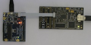
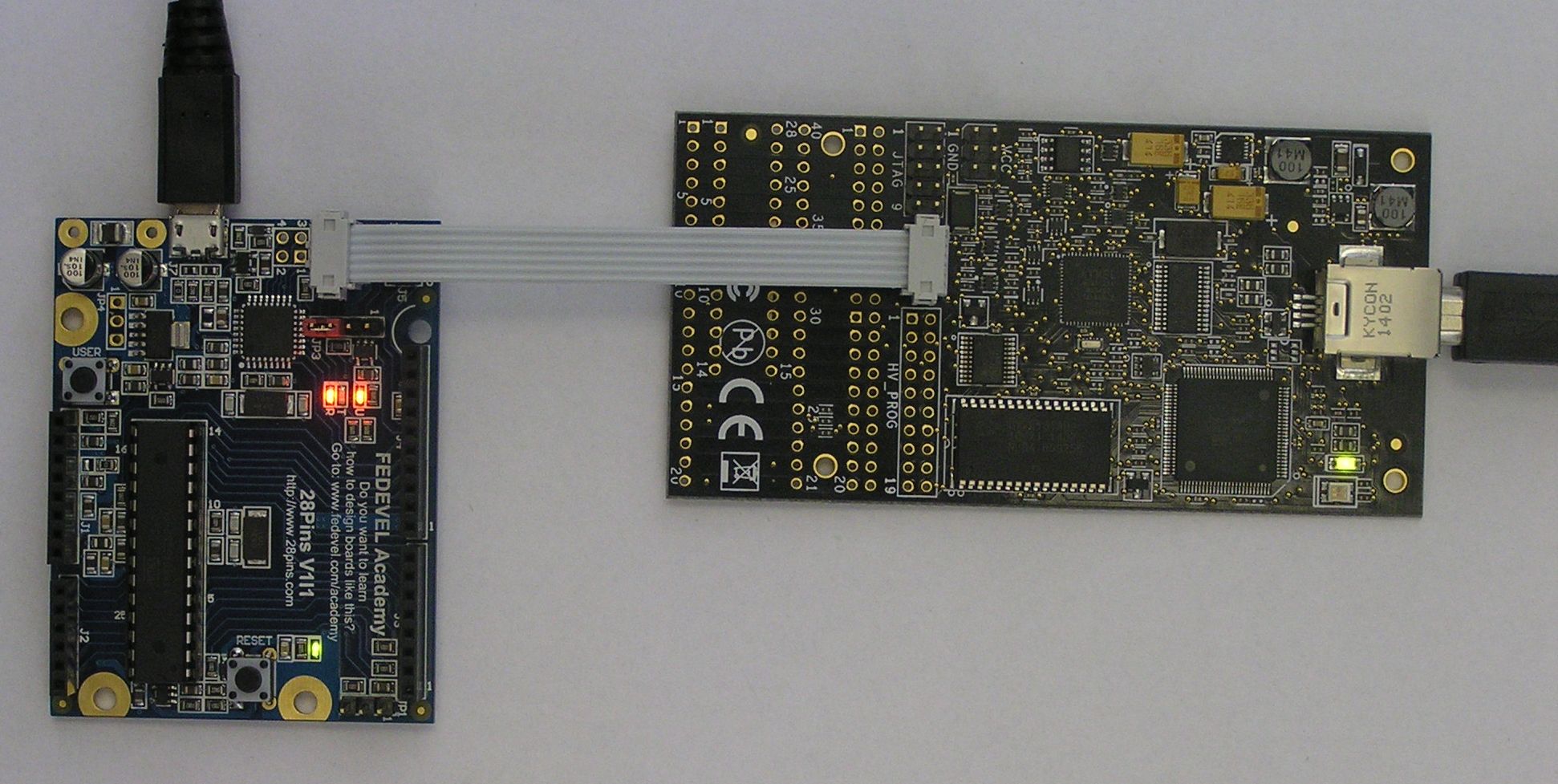
- Connect ATAVRDRAGON to your PC
- Take your 28Pins board and fit a Link on the JP3 to short pins 3-4. Unfit all the other Links.
- Connect 28Pins to your PC
- Connect ribbon cable between ATAVDRAGON ISP and 28Pins ICSP1. Be aware of pin number 1!
- Start Atmel Studio. Go to Start -> All Programs -> Atmel -> Atmel Studio
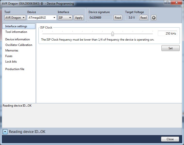
- Go to: Tools -> Device Programming
- Select: Tool AVR Dragon; Device ATmega16U2; Interface ISP; and press "Apply" button.
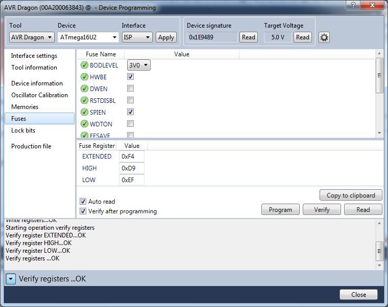
- Go to: Device signature and click on "Read" button.
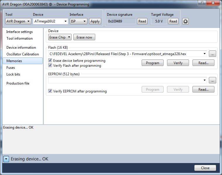
- Erase the chip: Click on Memories -> Device -> Erase Chip -> Erase now
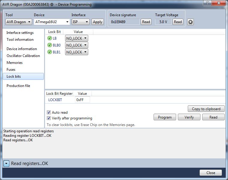
- Check the LOCK BITS: Click on "Lock bits". The LOCKBIT should be now 0xFF and everything should be NO_LOCK.
- Click on "Fuses". Set: EXTENDED = 0xF4; HIGH = 0xD9; LOW = 0xEF. Press "Program" button
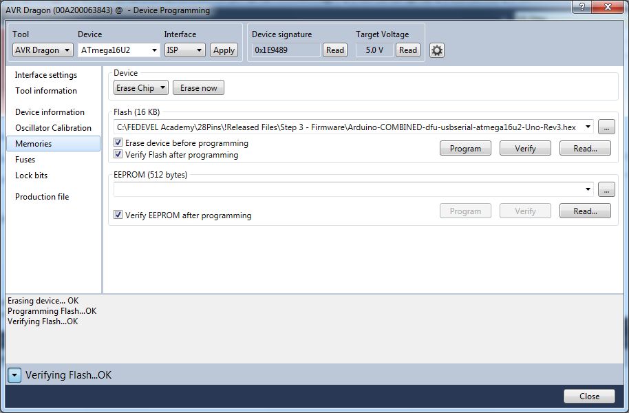
- Click on "Memories". Find and select Arduino-COMBINED-dfu-usbserial-atmega16u2-Uno-Rev3.hex then press "Program" button.
- You have successfully updated default settings of 16U2.
In this step we are going to change 16U2 firmware. After the firmware update 16U2 becomes MKII programmer.
- Fit a Link on the JP1 to short pins 2-3 (this link puts HWB pin Low tu support DFU mode).
- Connect an USB cable between 28Pins and your PC.
- A new USB device should be recognized (16U2 is in DFU mode).
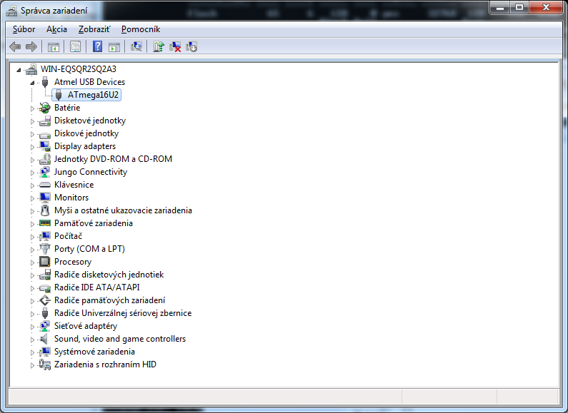
- Install Driver. It is located in "c:\Program Files\Atmel\Flip 3.4.7\usb\"
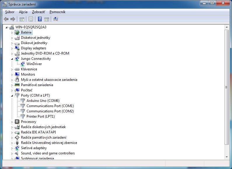
- Go to Device Manager (press Win+Pause -> (Hardware) -> Device Manager ) and check if you can see the driver properly installed. It will be under Atmel USB Devices -> ATmega16U2
- Start FLIP software (Start -> All Programs -> Flip -> Flip)
- Go to Settings -> Communication -> USB
- Press "Open".
- Go to File -> Load HEX file and select LUFA-AVRISP-MKII.hex
- Press "Run".
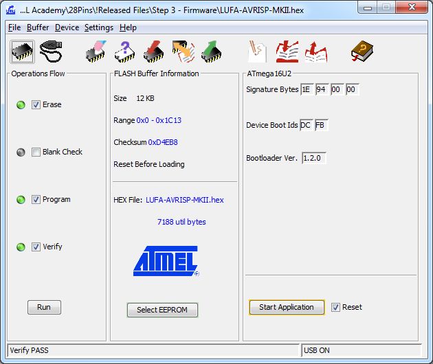
- The 16U2 is now AVRISP MKII. Disconnect the USB cable.
In this step, we will flash the Arduino bootloader into ATMEGA328P through ATMEGA16U2.
- Connect a ribbon cable between ICSP and ICSP1 connectors. This will connect MOSI, MISO and CLK pins between 16U2 and 328P.
- Fit JP3 jumper the way it shorts pins 2-3. This will connect 16U2 PB4 to RESET of 328P.
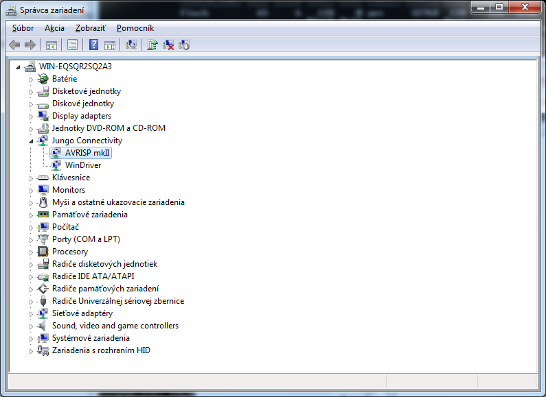
- Connect 28Pins to USB. The RX&TX LEDs should blink two times. Drivers should be correctly recognized (Jungo Connectivity -> AVRISP mkII)
- Start Atmel Studio. Go to Start -> All Programs -> Atmel -> Atmel Studio
- Go to: Tools -> Device Programming
- Select: Tool AVRISP mkII; Device ATmega328P; Interface ISP; and press "Apply" button.
- Go to: Device signature and click on "Read" button.
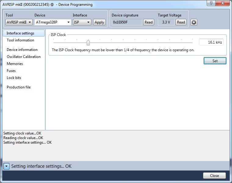
- Important: Set the ISP clock to 16.1kHz. Don't forget to click on the "Set" button.
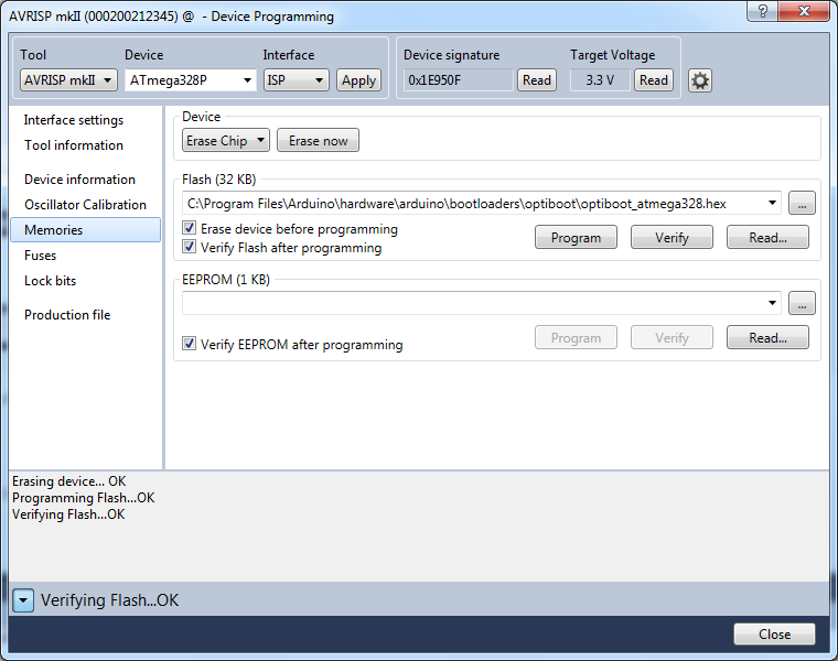
- Click on "Lock bits" and be sure they are all NO_LOCK (LOCKBIT = 0xFF)

- Click on "Fuses" and set them as: EXTENDED = 0xFD; HIGH = 0xDE; LOW = 0xFF. Click on button "Program"

- Click on "Memories" and find the Arduino bootloader hex file. It is located in "C:\Program Files\Arduino\hardware\arduino\bootloaders\optiboot\optiboot_atmega328.hex"
- Press "Program" button
- You have successfully programmed 328P with Arduino bootloader. Now we need to re-flash 16U2 to become USB to Serial translator.
In this step we are going to flash Serial to USB firmware into the 16U2. We will use FLIP again.
- Fit a Link on the JP1 to short pins 2-3.
- Connect the USB cable.
- Start FLIP software. Go to: Start -> All Programs -> Flip -> Flip
- Go to: Settings -> Communication -> USB
- Click to "Open".
- Go to: File -> Load HEX file. Select this file "c:\Program Files\Arduino\hardware\arduino\firmwares\atmegaxxu2\arduino-usbserial\Arduino-usbserial-atmega16u2-Uno-Rev3.hex"
- Press "Run".
- Your 28Pins is now software compatible with Arduino board.
We are going to upload Arduino "Blink" example to test the board.
- Fit a Link on the JP1 to short pins 1-2.
- Connect the USB cable.
- A new USB device should be recognized. If driver is not installed automatically, you will find it in "c:\Program Files\Arduino\drivers\".
- Go to Device manager (Win+Pause -> (Hardware) -> Device manager) and check if the driver was loaded correctly. You should see it under Ports -> Arduino Uno
- Start Arduino software (Start -> Arduino).
- Click on the "Open" icon (arrow Up) -> 01.Basics -> Blink.
- Select COM Port: Tools -> Serial Port -> COM(select the port where the board was recognized).
- Click to "Upload" icon (arrow Right).
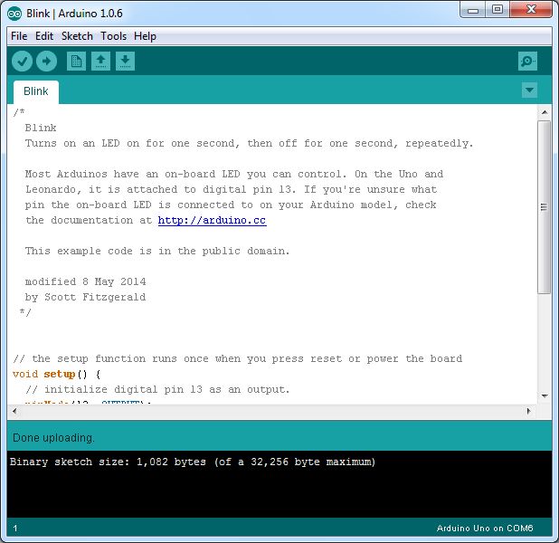
- The user LED should start blinking

- Well done! You have successfully programmed both, ATMEGA16U2 and ATMEGA328P microcontrollers.