
On this page you will learn how to update firmware inside ATMEGA16U2, so it becomes "AVRISP MKII" programmer. Then we will use it to program ATMEGA328P chip. You can do similar steps also with your Arduino Uno R3 board, that's how I initially tested it.
Content
How does it work: There are two microcontrollers on the 28Pins - ATMEGA16U2 (16U2) and ATMEGA328P (328P). In the "Arduino" compatible mode, 16U2 works like USB to Serial translator. However, by changing the firmware inside 16U2, we can make it to become a programmer or even a debugger. For example, when we put AVRISP MKII firmware inside the 16U2, then it becomes AVRISP MKII programmer and 16U2 can be used to program other chips through ICSP1, even the 328P on board microcontroller. In this case, connect ICSP1 header to your target and be sure the JP3 jumper is placed on the pins 2-3 (JP3 will connect PB4 pin of 16U2 to the ICSP1 header, so 16U2 can drive RESET signal of the connected device). Then just use Atmel Studio (or other software) to program the target. Below are the exact steps how to do it.
To download a firmware into ATMEGA16U2, you will need a software called FLIP:
- Download FLIP from http://www.atmel.com/tools/FLIP.aspx
- Install the FLIP (just follow the installation wizard).
- Fit a Link on the JP1 to short pins 2-3 (this link puts HWB pin Low tu support DFU mode).
- Fit a Link on ICSP1 to short pins 5-6 (this link shorts 16U2 RESET to GND).
- Connect an USB cable between 28Pins and your PC.
- Unfit the ICSP1(5-6) Link. A new USB device should be recognized (16U2 is in DFU mode).
- Install Driver. It is located in "c:\Program Files\Atmel\Flip 3.4.7\usb\"
- Go to Device Manager (press Win+Pause -> (Hardware) -> Device Manager ) and check if you can see the driver properly installed. It will be under Atmel USB Devices -> ATmega16U2
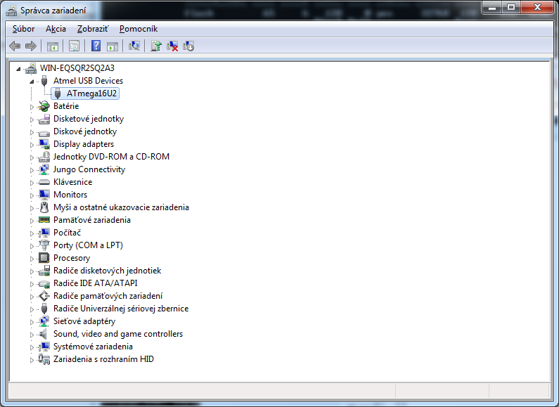
- You are now ready to flash ATMEGA16U2.
Now we are going to flash a firmware into the ATMEGA16U2:
- Download AVRISP MKII hex file.
This is important: There are three different AVRISP MKII hex files on the Internet - one is for Avrdude (also used by Arduino), one is for ATMEL Studio and one is for BOTH. We will use the firmware for BOTH. Note: I created this hex file from LUFA Project. Check out Appendix how you can compile it by yourself. - Disconnect 28Pins from the USB cable.
- Fit a Link on the JP1 to short pins 2-3.
- Fit the ICSP1(5-6) Link.
- Connect the USB cable.
- Unfit the ICSP1(5-6) Link.
- Start FLIP software (Start -> All Programs -> Flip -> Flip)
- Go to Settings -> Communication -> USB
- Press "Open".
- Go to File -> Load HEX file and select LUFA-AVRISP-MKII.hex
- Press "Run".
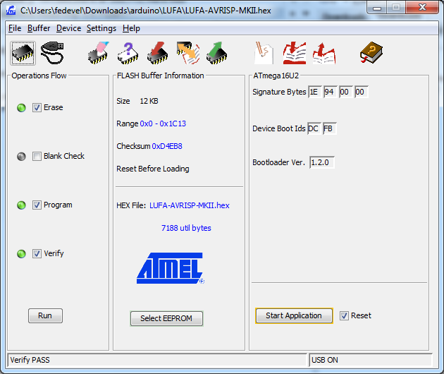
- The 16U2 now becomes AVRISP MKII. Disconnect the USB cable.
This is the tricky part and I spent quite a time to figure it out how it works. The problem is, that you may want to use two different drivers: one for Avrdude (used by Arduino) and a different driver for Atmel Studio. To make it even more complicated, there is some incompatibility between different Avrdude versions (the LUFA AVRISP MKII firmware may not work with the Avrdude 6 version, see this Avrdude Bug #40831). In the next steps I described how to use Atmel Studio. Note: You can switch between Atmel Studio and Avrdude mode. Each time the 16U2 is reset externally via the reset pin (ICSP1 pins 5-6, JP1 must be on 1-2), the compatibility mode will be toggled. You can recognize the current mode when you connect the board to USB: RX&TX LEDs will flash twice on startup for Atmel Studio mode, and five times for avrdude mode.
Important: After you flash the LUFA-AVRISP-MKII, the ATMEGA16U2 is configured for ATMEL Studio.
- Download and Install ATMEL Studio from http://www.atmel.com/microsite/atmel_studio6/ When asked, install also all the drivers.
- After the installation, connect 28pins to the USB cable. Both LEDs (RX&TX) should blink two times (that means, 16U2 is in "Atmel Studio" mode,). A new device will be recognized.
- Install drivers. If they are not recognized automatically, you will find them in "c:\Program Files\Atmel\Atmel USB Drivers\"
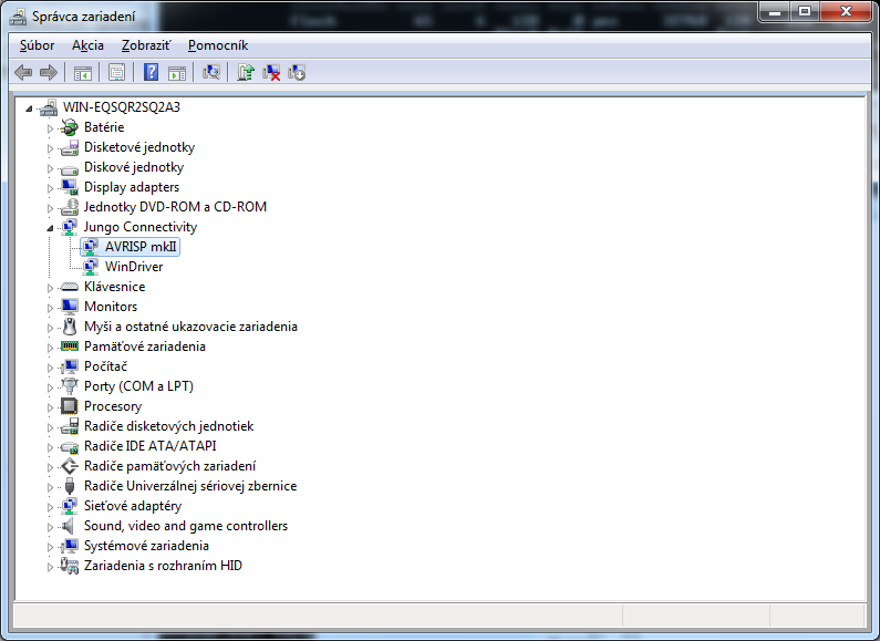
- Go to Device Manager (press Win+Pause -> (Hardware) -> Device Manager ) and check if you can see the driver properly installed. It will be under Jungo Connectivity -> AVRISP mkII
- Now you can use 28Pins as a standard AVRISP MKII to flash other boards and chips. In the next step we will flash ATMEGA328P with a bootloader
In this step, we will flash the Arduino bootloader into ATMEGA328P through ATMEGA16U2.
- Be sure your 28pins board is correctly recognized and installed for using with Atmel Studio. See the previous steps.
- Connect a ribbon cable between ICSP and ICSP1 connectors. This will connect MOSI, MISO and CLK pins between 16U2 and 328P.
- Fit JP3 jumper the way it shorts pins 2-3. This will connect 16U2 PB4 to RESET of 328P.
- Connect 28Pins to USB. The RX&TX LEDs should blink two times. Drivers should be correctly recognized (Jungo Connectivity -> AVRISP mkII)
- Start Atmel Studio. Go to Start -> All Programs -> Atmel -> Atmel Studio
- Go to: Tools -> Device Programming
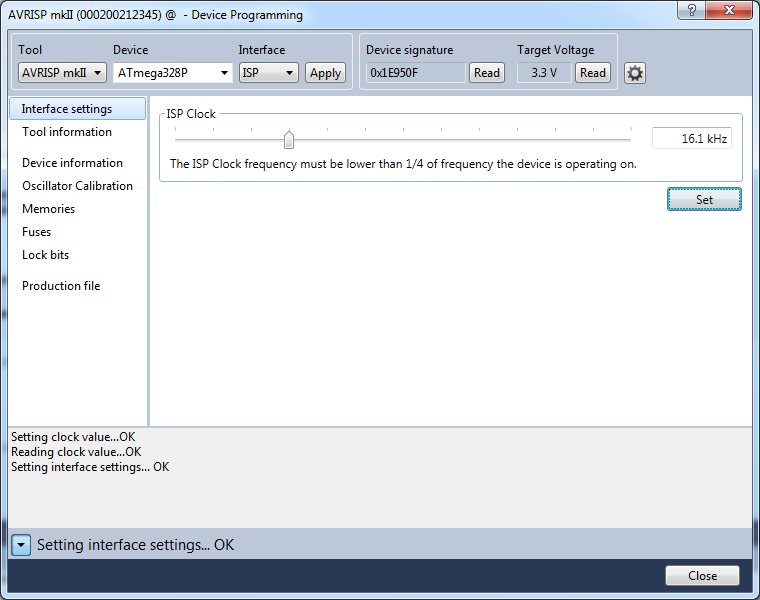
- Select: Tool AVRISP mkII; Device ATmega328P; Interface ISP; and press "Apply" button.
- Go to: Device signature and click on "Read" button.
- Important: Set the ISP clock to 16.1kHz. Don't forget to click on the "Set" button.
Note: I had a look into LUFA AVRISP MKII source code and there is hardcoded maximum waiting time. This means, programming will not work if you set a very low ISP clock speed. You will get error: "ispProgramMem: Error status received: Got 0x81, expected 0x00 (RDY/nBSY pin sampling timed out)". However, the maximum ISP speed is also limited and it can not be more than 1/4 frequency of the device.
- Click on "Memories" and find the Arduino bootloader hex file. It is located in "C:\Program Files\Arduino\hardware\arduino\bootloaders\optiboot\optiboot_atmega328.hex"
- Press "Program" button
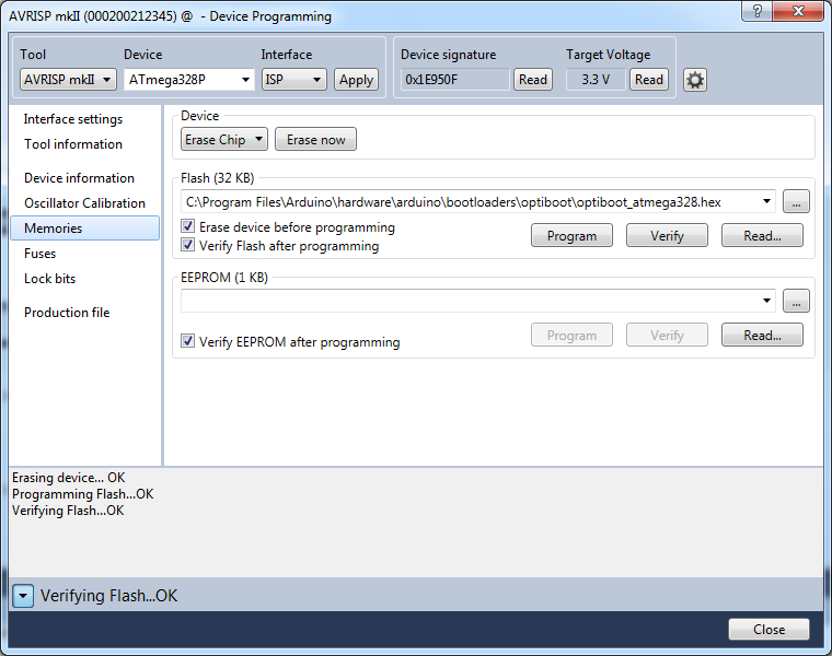
- Done. You have successfully programmed 328P with Arduino bootloader. If you would like to use 28Pins with Arduino Software, read further. You will need to re-flash 16U2 with USB to serial firmware.
If you would like to use 28Pins with Arduino software, you will need to flash Serial to USB firmware into the 16U2. We will use FLIP again.
- Disconnect 28Pins from the USB cable.
- Fit a Link on the JP1 to short pins 2-3.
- Fit the ICSP1(5-6) Link.
- Connect the USB cable.
- Unfit the ICSP1(5-6) Link.
- Start FLIP software. Go to: Start -> All Programs -> Flip -> Flip
- Go to: Settings -> Communication -> USB
- Click to "Open".
- Go to: File -> Load HEX file. Select this file "c:\Program Files\Arduino\hardware\arduino\firmwares\atmegaxxu2\arduino-usbserial\Arduino-usbserial-atmega16u2-Uno-Rev3.hex"
- Press "Run".
- Disconnect USB cable and connect it again. A new USB device should be recognized. If driver is not installed automatically, you will find it in "c:\Program Files\Arduino\drivers\".
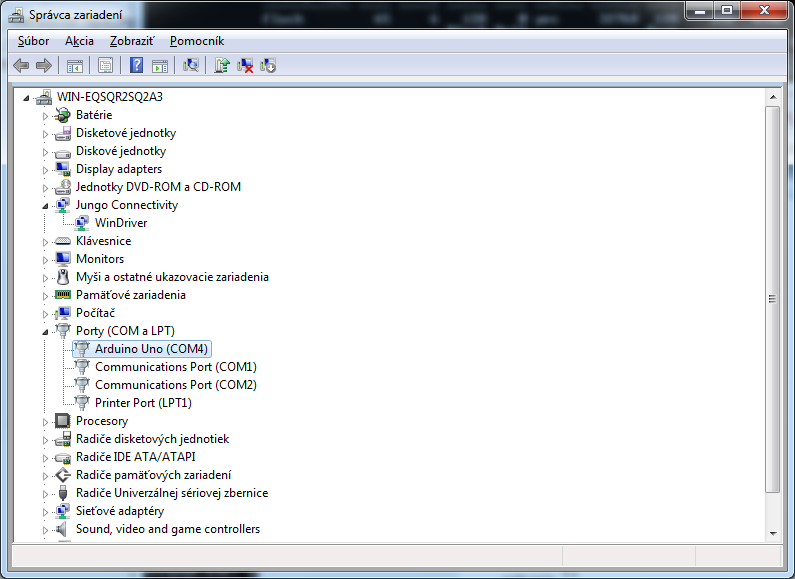
- Go to Device manager (Win+Pause -> (Hardware) -> Device manager) and check if the driver was loaded correctly. You should see it under Ports -> Arduino Uno
- Great! We can now test a Blink example. Start Arduino software (Start -> Arduino).
- Click on the "Open" icon (arrow Up) -> 01.Basics -> Blink.
- Select COM Port: Tools -> Serial Port -> COM(select the port where the board was recognized).
- Be sure, that JP1 shorts pins 1-2 (Autoreset is enabled).
- Click to "Upload" icon (arrow Right).
- The user LED should start blinking

- Well done! You have successfully programmed both, ATMEGA16U2 and ATMEGA328P microcontrollers.
Appendix
To compile AVRISP MKII you need a Linux computer. If you are a Windows user, install a virtual machine:
- Download VMware player (it's free).
- Download and Install Ubuntu 12.04 into the vMware virtual machine
- Update sources.list
sudo gedit /etc/apt/sources.list
Replace the source.list content with:
# deb cdrom:[Ubuntu 9.04 _Jaunty Jackalope_ - Release i386 (20090420.1)]/ jaunty main restricted
# See http://help.ubuntu.com/community/UpgradeNotes for how to upgrade to
# newer versions of the distribution.
deb http://old-releases.ubuntu.com/ubuntu/ jaunty main restricted
deb-src http://old-releases.ubuntu.com/ubuntu/ jaunty main restricted
## Major bug fix updates produced after the final release of the
## distribution.
deb http://old-releases.ubuntu.com/ubuntu/ jaunty-updates main restricted
deb-src http://old-releases.ubuntu.com/ubuntu/ jaunty-updates main restricted
## N.B. software from this repository is ENTIRELY UNSUPPORTED by the Ubuntu
## team. Also, please note that software in universe WILL NOT receive any
## review or updates from the Ubuntu security team.
deb http://old-releases.ubuntu.com/ubuntu/ jaunty universe
deb-src http://old-releases.ubuntu.com/ubuntu/ jaunty universe
deb http://old-releases.ubuntu.com/ubuntu/ jaunty-updates universe
deb-src http://old-releases.ubuntu.com/ubuntu/ jaunty-updates universe
## N.B. software from this repository is ENTIRELY UNSUPPORTED by the Ubuntu
## team, and may not be under a free licence. Please satisfy yourself as to
## your rights to use the software. Also, please note that software in
## multiverse WILL NOT receive any review or updates from the Ubuntu
## security team.
deb http://old-releases.ubuntu.com/ubuntu/ jaunty multiverse
deb-src http://old-releases.ubuntu.com/ubuntu/ jaunty multiverse
deb http://old-releases.ubuntu.com/ubuntu/ jaunty-updates multiverse
deb-src http://old-releases.ubuntu.com/ubuntu/ jaunty-updates multiverse
## Uncomment the following two lines to add software from the 'backports'
## repository.
## N.B. software from this repository may not have been tested as
## extensively as that contained in the main release, although it includes
## newer versions of some applications which may provide useful features.
## Also, please note that software in backports WILL NOT receive any review
## or updates from the Ubuntu security team.
# deb http://us.old-releases.ubuntu.com/ubuntu/ jaunty-backports main restricted universe multiverse
# deb-src http://us.old-releases.ubuntu.com/ubuntu/ jaunty-backports main restricted universe multiverse
## Uncomment the following two lines to add software from Canonical's
## 'partner' repository.
## This software is not part of Ubuntu, but is offered by Canonical and the
## respective vendors as a service to Ubuntu users.
# deb http://archive.canonical.com/ubuntu jaunty partner
# deb-src http://archive.canonical.com/ubuntu jaunty partner
deb http://old-releases.ubuntu.com/ubuntu/ jaunty-security main restricted
deb-src http://old-releases.ubuntu.com/ubuntu/ jaunty-security main restricted
deb http://old-releases.ubuntu.com/ubuntu/ jaunty-security universe
deb-src http://old-releases.ubuntu.com/ubuntu/ jaunty-security universe
deb http://old-releases.ubuntu.com/ubuntu/ jaunty-security multiverse
deb-src http://old-releases.ubuntu.com/ubuntu/ jaunty-security multiverse
- Upgrade to the latest packages
- Open up System \-> Administration \-> Update Manager
- Click on Settings.
- Open the Updates Tab.
- Set ‘Release upgrade’ to ‘Never’.
- Close the settings dialog box.
- Click on ‘Check’ to check for upgraded packages. It will look for packages that are upgraded from the version that is installed on your box.
- Choose to install the upgrades. This will take a while on a freshly installed box.
- The Linux machine is ready, now we need to prepare the AVR compiler
To compile an AVR source code, you will need to install Atmel AVR Toolchain.
- Go to http://www.atmel.com/tools/atmelavrtoolchainforlinux.aspx and download the toolchain.
- Unzip the file
$ cd
$ mkdir atmel $ cd Downloads
$ tar -xvzf avr8-gnu-toolchain-3.4.5.1522-linux.any.x86.tar.gz
$ mv avr8-gnu-toolchain-linux_x86/ ../atmel
- Update the PATH
$ export PATH=$PATH:~/atmel/avr8-gnu-toolchain-linux_x86/bin/
- Check if the compiler is accessible
$ avr-gcc --version
avr-gcc (AVR_8_bit_GNU_Toolchain_3.4.5_1522) 4.8.1
Copyright (C) 2013 Free Software Foundation, Inc.
This is free software; see the source for copying conditions. There is NO
warranty; not even for MERCHANTABILITY or FITNESS FOR A PARTICULAR PURPOSE.
To generate the AVRISP MKII hex file, we will need to download LUFA source codes, modify AVRISP MKII project and compile it.
- Download LUFA Project here: http://www.github.com/abcminiuser/lufa/archive/LUFA-140928.zip
- Unzip the file:
$ cd Downloads
$ unzip lufa-LUFA-140928.zip
$ mv lufa-LUFA-140928/ ../atmel
- Test if the original source code will compile correctly:
$ cd
$ cd atmel/lufa-LUFA-140928/Projects/AVRISP-MKII/
$ make clean
$ make all
When it compiles correctly, you should see something like:
...
avr-size --mcu=at90usb1287 --format=avr AVRISP-MKII.elf
AVR Memory Usage
----------------
Device: at90usb1287

Program: 10570 bytes (8.1% Full)
(.text + .data + .bootloader)

Data: 179 bytes (2.2% Full)
(.data + .bss + .noinit)

EEPROM: 2 bytes (0.0% Full)
(.eeprom)

[INFO] : Finished building project "AVRISP-MKII".
- We are going to make few changes. First, we need to change the original microcontroller to our ATMEGA16U2:
$ gedit makefile
Change MCU, BOARD and F_CPU to following:
#
# LUFA Library
# Copyright (C) Dean Camera, 2014.
#
# dean [at] fourwalledcubicle [dot] com
# www.lufa-lib.org
#
# --------------------------------------
# LUFA Project Makefile.
# --------------------------------------

# Run "make help" for target help.

MCU = atmega16u2
ARCH = AVR8
BOARD = USBTINYMKII
F_CPU = 16000000
F_USB = $(F_CPU)
OPTIMIZATION = s
TARGET = AVRISP-MKII
SRC = $(TARGET).c AVRISPDescriptors.c Lib/V2Protocol.c Lib/V2ProtocolParams.c Lib/ISP/ISPProtocol.c Lib/ISP/ISPTarget.c Lib/XPROG/XPROGProtocol.c \
Lib/XPROG/XPROGTarget.c Lib/XPROG/XMEGANVM.c Lib/XPROG/TINYNVM.c $(LUFA_SRC_USB)
LUFA_PATH = ../../LUFA
CC_FLAGS = -DUSE_LUFA_CONFIG_HEADER -IConfig/
LD_FLAGS =

# Default target
all:

# Include LUFA build script makefiles
include $(LUFA_PATH)/Build/lufa_core.mk
include $(LUFA_PATH)/Build/lufa_sources.mk
include $(LUFA_PATH)/Build/lufa_build.mk
include $(LUFA_PATH)/Build/lufa_cppcheck.mk
include $(LUFA_PATH)/Build/lufa_doxygen.mk
include $(LUFA_PATH)/Build/lufa_dfu.mk
include $(LUFA_PATH)/Build/lufa_hid.mk
include $(LUFA_PATH)/Build/lufa_avrdude.mk
include $(LUFA_PATH)/Build/lufa_atprogram.mk
Change AppConfig.h:
$ gedit Config/AppConfig.h
Disable XPROG, enable NO VTARGET, disable LIBUSB and enable RESET TOGGLES:
#ifndef _APP_CONFIG_H_
#define _APP_CONFIG_H_

#define AUX_LINE_PORT PORTB
#define AUX_LINE_PIN PINB
#define AUX_LINE_DDR DDRB
#if (BOARD == BOARD_U2S)
#define AUX_LINE_MASK (1 << 0)
#else
#define AUX_LINE_MASK (1 << 4)
#endif

#define ENABLE_ISP_PROTOCOL
//#define ENABLE_XPROG_PROTOCOL

#define VTARGET_ADC_CHANNEL 2
#define VTARGET_REF_VOLTS 5
#define VTARGET_SCALE_FACTOR 1
//#define VTARGET_USE_INTERNAL_REF
#define NO_VTARGET_DETECT
//#define XCK_RESCUE_CLOCK_ENABLE
//#define INVERTED_ISP_MISO

//#define LIBUSB_DRIVER_COMPAT
#define RESET_TOGGLES_LIBUSB_COMPAT
//#define FIRMWARE_VERSION_MINOR 0x11
#endif
Now we will remap LEDs, so we can see if AVRISP MKII is in Avrdude or Atmel Studio mode. Edit LEDs file:
$ gedit ~/atmel/lufa-LUFA-140928/LUFA/Drivers/Board/AVR8/USBTINYMKII/LEDs.h
To make it simple, we just remap the ports, but the LEDs will be inverted (in the original USBTINYMKII board the LEDS are ON when pin is High, on the 28Pins LEDs are ON when pin is Low). Update the LED mask and Change all the DDRB / PORTB / PINB to to DDRD / PORTD / PIND. The file will then look like this:
#ifndef __LEDS_USBTINYMKII_H__
#define __LEDS_USBTINYMKII_H__

/* Includes: */
#include "../../../../Common/Common.h"

/* Enable C linkage for C++ Compilers: */
#if defined(__cplusplus)
extern "C" {
#endif

/* Preprocessor Checks: */
#if !defined(__INCLUDE_FROM_LEDS_H)
#error Do not include this file directly. Include LUFA/Drivers/Board/LEDS.h instead.
#endif

/* Public Interface - May be used in end-application: */
/* Macros: */
/** LED mask for the first LED on the board. */
#define LEDS_LED1        (1 << 4)

/** LED mask for the second LED on the board. */
#define LEDS_LED2        (1 << 5)

/** LED mask for the third LED on the board. */
#define LEDS_LED3        (1 << 6)

/** LED mask for all the LEDs on the board. */
#define LEDS_ALL_LEDS    (LEDS_LED1 | LEDS_LED2 | LEDS_LED3)

/** LED mask for none of the board LEDs. */
#define LEDS_NO_LEDS     0

/* Inline Functions: */
#if !defined(__DOXYGEN__)
static inline void LEDs_Init(void)
{
DDRD  |=  LEDS_ALL_LEDS;
PORTD &= ~LEDS_ALL_LEDS;
}

static inline void LEDs_Disable(void)
{
DDRD  &= ~LEDS_ALL_LEDS;
PORTD &= ~LEDS_ALL_LEDS;
}

static inline void LEDs_TurnOnLEDs(const uint8_t LedMask)
{
PORTD |= LedMask;
}

static inline void LEDs_TurnOffLEDs(const uint8_t LedMask)
{
PORTD &= ~LedMask;
}

static inline void LEDs_SetAllLEDs(const uint8_t LedMask)
{
PORTD = ((PORTD & ~LEDS_ALL_LEDS) | LedMask);
}

static inline void LEDs_ChangeLEDs(const uint8_t LedMask,
const uint8_t ActiveMask)
{
PORTD = ((PORTD & ~LedMask) | ActiveMask);
}

static inline void LEDs_ToggleLEDs(const uint8_t LEDMask)
{
PIND  = LEDMask;
}

static inline uint8_t LEDs_GetLEDs(void) ATTR_WARN_UNUSED_RESULT;
static inline uint8_t LEDs_GetLEDs(void)
{
return (PORTD & LEDS_ALL_LEDS);
}
#endif

/* Disable C linkage for C++ Compilers: */
#if defined(__cplusplus)
}
#endif

#endif
- We can now compile the project:
$ cd
$ cd atmel/lufa-LUFA-140928/Projects/AVRISP-MKII/
$ make clean
$ make all
It should look like this:
...
avr-size --mcu=atmega16u2 --format=avr AVRISP-MKII.elf
AVR Memory Usage
----------------
Device: atmega16u2

Program:    7176 bytes (43.8% Full)
(.text + .data + .bootloader)

Data:        123 bytes (24.0% Full)
(.data + .bss + .noinit)

EEPROM:        3 bytes (0.6% Full)
(.eeprom)

[INFO]    : Finished building project "AVRISP-MKII".
- Go to ~/atmel/lufa-LUFA-140928/Projects/AVRISP-MKII and you fill find there AVRISP-MKII.hex file. Copy this file to your computer and use FLIP Software to flash it inside the ATMEGA16U2. Here you can download the file I compiled: LUFA-BOTH-AVRISP-MKII.hex
Note: Initially 16U2 will run in the Atmel Studio mode, if you would like to change it, Fit and Unfit a Link on ICSP1 between pins 5-6 (this will reset the 16U2 and it will change the mode, you will see the LEDs blinking 4-5 times). If you are using Arduino Uno R3, you will need to pull HWB pin to +5V before you use the Reset Link, otherwise your 16U2 will go into DFU mode and will not toggle between Atmel Studio and Avrdude mode.